Auto Facial Animation - Head
The Head node corresponds to the Head animation morph from the default facial morphs for CC3+ characters.
The morph intensity is automatically converted into head rotation and tilt angles.
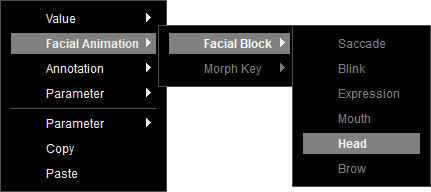
To create a Head node, right-click on the empty area of the graph, and select Facial Animation > Facial Block > Head from the context menu.
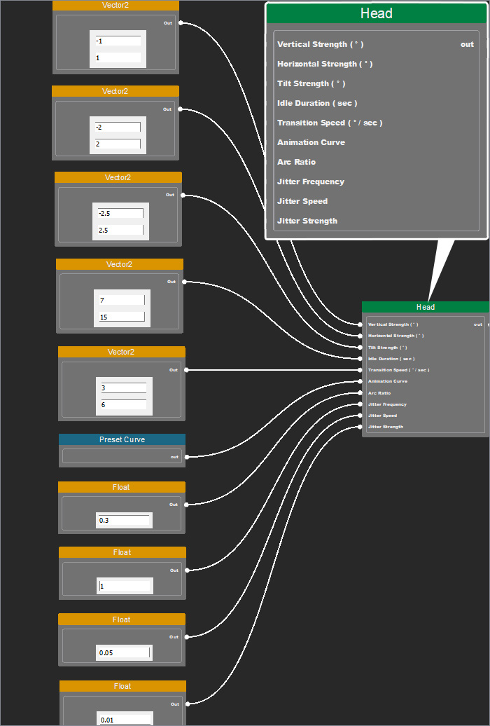
You can adjust the vertical strength, horizontal strength, tilt strength, idle duration, transition speed, animation curve, arc ratio, jitter frequency, jitter speed, and jitter strength via the Value nodes to control the animation results.
 Vertical Strength
Defines the allowed range for upward and downward head movement (corresponding to the "Head_Turn Up & Down" morph).
It accepts values input from the Vector2 node.
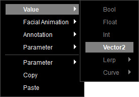
To create a Vector2 node, right-click on the empty area of the graph, and select Value > Vector2 from the context menu.
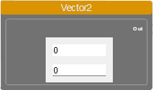
Specify the value range by defining a low and high value (in degrees) in the node.
For example, if the range is -50 to 50, each head animation will randomly pick a rotation value between -50° (upward) and 50° (downward).
Connect the Vector2 node to the Vertical Strength input of the Head node.
To create a Vector2 node, right-click on the empty area of the graph, and select Value > Vector2 from the context menu.
Specify the value range by defining a low and high value (in degrees) in the node.
For example, if the range is -50 to 50, each head animation will randomly pick a rotation value between -50° (upward) and 50° (downward).
Connect the Vector2 node to the Vertical Strength input of the Head node.
Horizontal Strength
Defines the allowed range for left and right head movement (corresponding to the "Head_Turn L & R" morph).
It accepts values input from the Vector2 node.
To create a Vector2 node, right-click on the empty area of the graph, and select Value > Vector2 from the context menu.
Specify the value range by defining a low and high value (in degrees) in the node.
For example, if the range is -50 to 50, the head will rotate between -50° (left) and 50° (right).
Connect the Vector2 node to the Horizontal Strength input of the Head node.
To create a Vector2 node, right-click on the empty area of the graph, and select Value > Vector2 from the context menu.
Specify the value range by defining a low and high value (in degrees) in the node.
For example, if the range is -50 to 50, the head will rotate between -50° (left) and 50° (right).
Connect the Vector2 node to the Horizontal Strength input of the Head node.
Tilt Strength
Defines the allowed range for left and right head tilt (corresponding to the "Head_Tilt L & R" morph).
It accepts values input from the Vector2 node.
To create a Vector2 node, right-click on the empty area of the graph, and select Value > Vector2 from the context menu.
Specify the value range by defining a low and high value (in degrees) in the node.
For example, if the range is -15 to 15, the head will tilt between -15° (left) and 15° (right).
Connect the Vector2 node to the Tilt Strength input of the Head node.
To create a Vector2 node, right-click on the empty area of the graph, and select Value > Vector2 from the context menu.
Specify the value range by defining a low and high value (in degrees) in the node.
For example, if the range is -15 to 15, the head will tilt between -15° (left) and 15° (right).
Connect the Vector2 node to the Tilt Strength input of the Head node.
Idle Duration
Defines the duration the head remains in a target position after reaching it.
It accepts values input from the Vector2 node.
To create a Vector2 node, right-click on the empty area of the graph, and select Value > Vector2 from the context menu.
Specify the value range by defining a low and high value (in seconds) in the node.
For example, if the range is 2 to 4 seconds, after moving to its target position, the head will hold the pose for a randomly chosen duration between 2 and 4 seconds.
Connect the Vector2 node to the Idle Duration input of the Head node.
To create a Vector2 node, right-click on the empty area of the graph, and select Value > Vector2 from the context menu.
Specify the value range by defining a low and high value (in seconds) in the node.
For example, if the range is 2 to 4 seconds, after moving to its target position, the head will hold the pose for a randomly chosen duration between 2 and 4 seconds.
Connect the Vector2 node to the Idle Duration input of the Head node.
Transition Speed
Defines the time taken to move from the current head position to the next target position.
It accepts values input from the Vector2 node.
To create a Vector2 node, right-click on the empty area of the graph, and select Value > Vector2 from the context menu.
Specify the value range by defining a low and high value (in seconds) in the node.
For example, if the range is 2 to 4 seconds, each head animation will take between 2 and 4 seconds to complete its transition.
Connect the Vector2 node to the Transition Speed input of the Head node.
To create a Vector2 node, right-click on the empty area of the graph, and select Value > Vector2 from the context menu.
Specify the value range by defining a low and high value (in seconds) in the node.
For example, if the range is 2 to 4 seconds, each head animation will take between 2 and 4 seconds to complete its transition.
Connect the Vector2 node to the Transition Speed input of the Head node.
Animation Curve
Controls how smoothly the head transitions between movements.
It accepts a preset animation curve from the Preset Curve node.
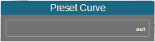
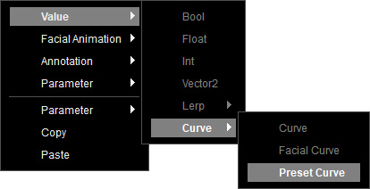
To create a Preset Curve node, right-click on the empty area of the graph, and select Value > Curve > Preset Curve from the context menu.
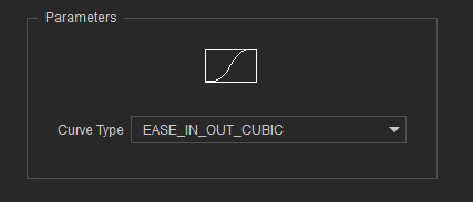
Select this node, and choose a curve type from the drop-down list in the Parameters section.
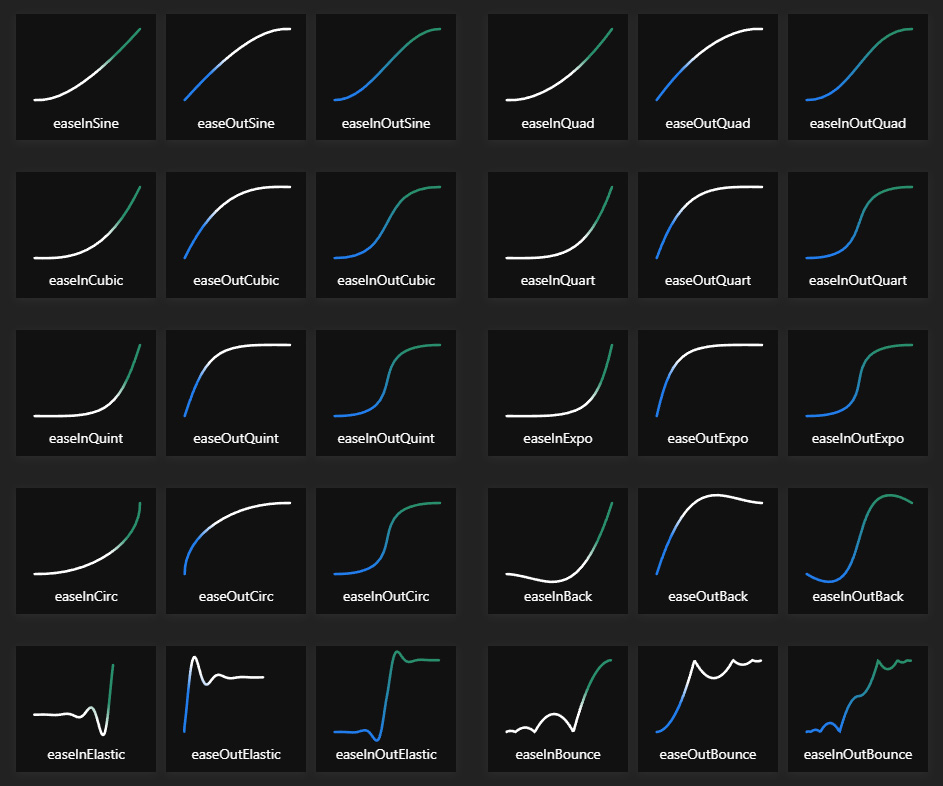
For more information on the different curve types, see easing styles.
Connect the Preset Curve node to the Animation Curve input of the Head node.
To create a Preset Curve node, right-click on the empty area of the graph, and select Value > Curve > Preset Curve from the context menu.
Select this node, and choose a curve type from the drop-down list in the Parameters section.
For more information on the different curve types, see easing styles.
Connect the Preset Curve node to the Animation Curve input of the Head node.
Arc Ratio
Defines the visual curvature of head movement, based on direction and input value.
It accepts values input from the Float node.
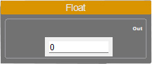
To create a Float node, right-click on the empty area of the graph, and select Value > Float from the context menu.

Set a numeric value ranging from 0 to 1 (higher values create larger arcs) with up to two decimal places in the node.
For example, you can create directional arcs for left-right head movements.
Connect the Float node to the Arc Ratio input of the Head node.
To create a Float node, right-click on the empty area of the graph, and select Value > Float from the context menu.
Set a numeric value ranging from 0 to 1 (higher values create larger arcs) with up to two decimal places in the node.
For example, you can create directional arcs for left-right head movements.
- Creates a downward arc for left/right movement.
- Creates a rightward arc for right-side downward movement.
- Creates a leftward arc for left-side downward movement.
Connect the Float node to the Arc Ratio input of the Head node.
Jitter Frequency
The IAA system uses Perlin Noise sampling to layer on randomized micro-movements (Jitter - Micro Head Shaking) on top of the head animation results (user-defined strength settings for X, Y, and Tilt axes).
This node controls the time interval between Perlin Noise outputs to directly affect the second-layer head animation frequency.
It accepts values input from the Float node.
To create a Float node, right-click on the empty area of the graph, and select Value > Float from the context menu.
Set a numeric value with up to two decimal places in the node.
For example, if it set to 1, the Perlin Noise interval remains unchanged, while it set to 0.5, the Perlin Noise output slows down by half.
Connect the Float node to the Jitter Frequency input of the Head node.
To create a Float node, right-click on the empty area of the graph, and select Value > Float from the context menu.
Set a numeric value with up to two decimal places in the node.
For example, if it set to 1, the Perlin Noise interval remains unchanged, while it set to 0.5, the Perlin Noise output slows down by half.
Connect the Float node to the Jitter Frequency input of the Head node.
Jitter Speed
The IAA system uses Perlin Noise sampling to layer on randomized micro-movements (Jitter - Micro Head Shaking) on top of the head animation results (user-defined strength settings for X, Y, and Tilt axes).
This node controls the rate of change in Perlin Noise outputs to affect the speed of micro head movements.
It accepts values input from the Float node.
To create a Float node, right-click on the empty area of the graph, and select Value > Float from the context menu.
Set a numeric value with up to two decimal places in the node.
For example, if it set to 0.1, each Perlin Noise update changes at only 10% of the previous value.
Connect the Float node to the Jitter Speed input of the Head node.
To create a Float node, right-click on the empty area of the graph, and select Value > Float from the context menu.
Set a numeric value with up to two decimal places in the node.
For example, if it set to 0.1, each Perlin Noise update changes at only 10% of the previous value.
Connect the Float node to the Jitter Speed input of the Head node.
Jitter Strength
The IAA system uses Perlin Noise sampling to layer on randomized micro-movements (Jitter - Micro Head Shaking) on top of the head animation results (user-defined strength settings for X, Y, and Tilt axes).
This node controls the intensity of Perlin Noise output as a percentage strength value to directly influence how strong the second-layer head movements appear.
It accepts values input from the Float node.
To create a Float node, right-click on the empty area of the graph, and select Value > Float from the context menu.
Set a numeric value with up to two decimal places in the node.
For example, if it set to 0.05, the next Perlin Noise value will only apply 5% of its computed strength to the head movement.
Connect the Float node to the Jitter Strength input of the Head node.
To create a Float node, right-click on the empty area of the graph, and select Value > Float from the context menu.
Set a numeric value with up to two decimal places in the node.
For example, if it set to 0.05, the next Perlin Noise value will only apply 5% of its computed strength to the head movement.
Connect the Float node to the Jitter Strength input of the Head node.
Using Lerp
In additional to the values input from Vector2, you can use Lerp to design the range of random animations.
The Lerp (linear Interpolate) is a mathematical operation node to find an interpolated value between two inputs.
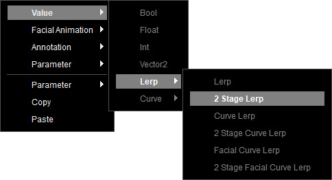
For example, create a 2 Stage Lerp node from the context menu Value > Lerp > 2 Stage Lerp to control the vertical strength of head.
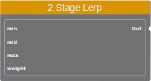
The 2 Stage Lerp node provides 3 input ports: min, mid and max for three different ranges, input from the Float or Vector2 node.
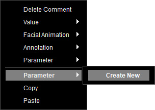
It requires a parameter node to control the weight for output. You can create one by right-clicking on the empty area of the graph, and selecting Parameter > Create New from the context menu.
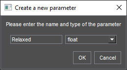
Name the new parameter and choose the float type. Click on OK.
Select this node to set a value ranging from 0 to 1 in the Variables section, to perform linear interpolation between the values from min to max. Once executed, the interpolated result is computed and sent to the connected nodes.
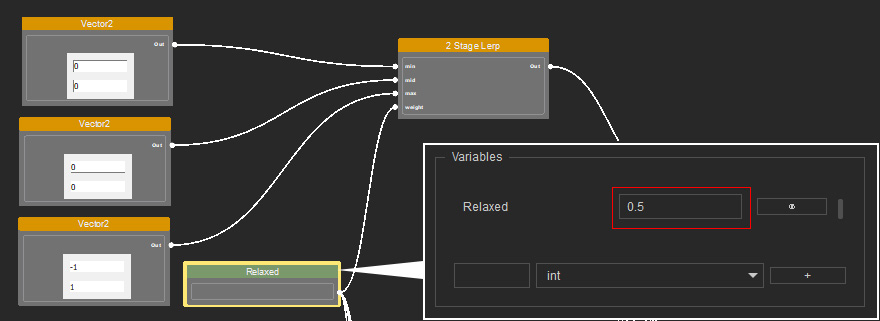
For example, create a 2 Stage Lerp node from the context menu Value > Lerp > 2 Stage Lerp to control the vertical strength of head.
The 2 Stage Lerp node provides 3 input ports: min, mid and max for three different ranges, input from the Float or Vector2 node.
It requires a parameter node to control the weight for output. You can create one by right-clicking on the empty area of the graph, and selecting Parameter > Create New from the context menu.
Name the new parameter and choose the float type. Click on OK.
Select this node to set a value ranging from 0 to 1 in the Variables section, to perform linear interpolation between the values from min to max. Once executed, the interpolated result is computed and sent to the connected nodes.
- If the value is set to 0, the result equals min.
- If the value is set to 0.5, the result equals mid.
- If the value is set to 1, the result equals max.
Make sure that the data are properly input in the Value nodes, before linking Head node to the root Auto Facial Animation node.
