Driven Animation Sources - Blink
The Blink node processes the procedural blink animation based on the input values, calculating the result on each execution and outputting it to an animation trigger.
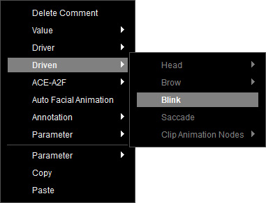
To create a Blink node, right-click on the empty area of the graph, and select Driven > Blink from the context menu.
You can feed value nodes into the various Blink inputs.
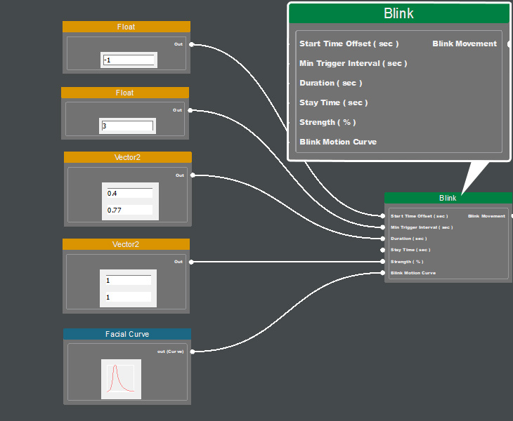
 Start Time Offset
Defines the time offset for triggering the blink motion (either in advance or delayed).
It accepts values from the Float node.
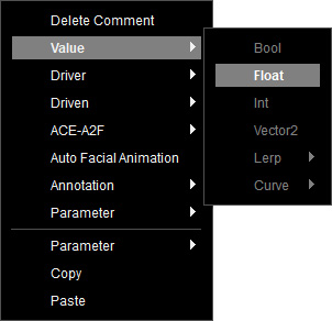
To create a Float node, right-click on the empty area of the graph, and select Value > Float from the context menu.
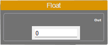
Set a numeric value (in seconds) up to 2 decimal places in precision. Upon execution, the configured value will be transmitted to connected nodes.
Connect the Float node to the Start Time Offset input of the Blink node.
To create a Float node, right-click on the empty area of the graph, and select Value > Float from the context menu.
Set a numeric value (in seconds) up to 2 decimal places in precision. Upon execution, the configured value will be transmitted to connected nodes.
Connect the Float node to the Start Time Offset input of the Blink node.
Min Trigger Interval
Defines the minimum time interval between two consecutive blink motions.
If the next blink occurs within this interval, it will be skipped.
It accepts values from the Float node.
To create a Float node, right-click on the empty area of the graph, and select Value > Float from the context menu.
Set a numeric value (in seconds) up to 2 decimal places in precision. Upon execution, the configured value will be transmitted to connected nodes.
Connect the Float node to the Min Trigger Interval input of the Blink node.
To create a Float node, right-click on the empty area of the graph, and select Value > Float from the context menu.
Set a numeric value (in seconds) up to 2 decimal places in precision. Upon execution, the configured value will be transmitted to connected nodes.
Connect the Float node to the Min Trigger Interval input of the Blink node.
Duration
Sets the total duration of a single blink, with a random value selected from the defined range.
It accepts values from the Vector2 node.
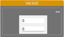
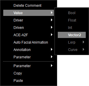
To create a Vector2 node, right-click on the empty area of the graph, and select Value > Vector2 from the context menu.
Specify the value range by defining a low and high value (in seconds) in the node. This node accepts two numerical inputs and generates a random value within the defined range. Once executed, it transmits the randomly selected result to the connected node.
Connect the Vector2 node to the Duration input of the Blink node.
To create a Vector2 node, right-click on the empty area of the graph, and select Value > Vector2 from the context menu.
Specify the value range by defining a low and high value (in seconds) in the node. This node accepts two numerical inputs and generates a random value within the defined range. Once executed, it transmits the randomly selected result to the connected node.
Connect the Vector2 node to the Duration input of the Blink node.
Stay Time
Defines the duration for which the eyelids remain closed after completing the "closing" motion.
It accepts values from the Vector2 node.
A random value is selected from the defined range.
To create a Vector2 node, right-click on the empty area of the graph, and select Value > Vector2 from the context menu.
Specify the value range by defining a low and high value (in seconds) in the node. This node accepts two numerical inputs and generates a random value within the defined range. Once executed, it transmits the randomly selected result to the connected node.
Connect the Vector2 node to the Stay Time input of the Blink node.
To create a Vector2 node, right-click on the empty area of the graph, and select Value > Vector2 from the context menu.
Specify the value range by defining a low and high value (in seconds) in the node. This node accepts two numerical inputs and generates a random value within the defined range. Once executed, it transmits the randomly selected result to the connected node.
Connect the Vector2 node to the Stay Time input of the Blink node.
Strength
Determines the percentage of eye coverage by the eyelids during each blink.
It accepts values from the Vector2 node.
A random value is selected within the defined range.
To create a Vector2 node, right-click on the empty area of the graph, and select Value > Vector2 from the context menu.
Specify the value range by defining a low and high value (in percentages) in the node. This node accepts two numerical inputs and generates a random value within the defined range. Once executed, it transmits the randomly selected result to the connected node.
Connect the Vector2 node to the Strength input of the Blink node.
To create a Vector2 node, right-click on the empty area of the graph, and select Value > Vector2 from the context menu.
Specify the value range by defining a low and high value (in percentages) in the node. This node accepts two numerical inputs and generates a random value within the defined range. Once executed, it transmits the randomly selected result to the connected node.
Connect the Vector2 node to the Strength input of the Blink node.
Blink Motion Curve
Defines the behavior and timing of blinking animations.
It accepts an animation curve from the Facial Curve node.
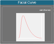
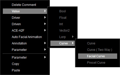
To create a Facial Curve node, right-click on the empty area of the graph, and select Value > Curve > Facial Curve from the context menu.
Select this node, and drag the Bezier curve along the X and Y axes in the Parameters section.
Connect the Facial Curve node to the Blink Motion Curve input of the Blink node.
To create a Facial Curve node, right-click on the empty area of the graph, and select Value > Curve > Facial Curve from the context menu.
Select this node, and drag the Bezier curve along the X and Y axes in the Parameters section.
- X Axis for Time Distribution: Defines the time distribution of closing and opening eyelids based on the result from Duration range.
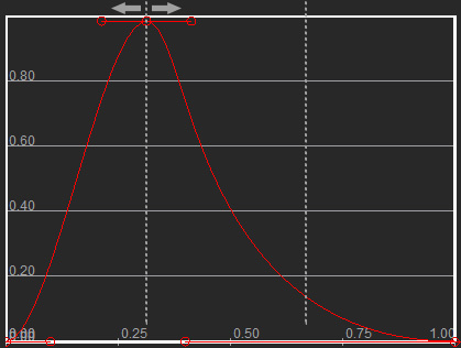
For example, if the total blink duration is 2 seconds, and the curve's closing-to-opening ratio is 1:2, the closing time will be 0.66 seconds, and the opening time will be 1.33 seconds. - Y Axis for Peak Strength Adjustment: Multiplies the result from Strength range with the curve’s peak value to determine the final blink intensity.
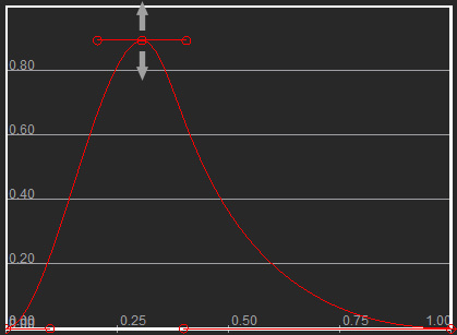
For example, If the blink intensity percentage is 0.8 (80%), and the curve peak value is 0.9, the final blink intensity will be 0.72 (72%).
Connect the Facial Curve node to the Blink Motion Curve input of the Blink node.
Using Lerp
In additional to the values input from Facial Curve to design the range of random animations.
The Lerp (linear Interpolate) is a mathematical operation node to find an interpolated value between two inputs.
For example, create a Facial Curve Lerp node from the context menu Value > Lerp > Facial Curve Lerp to control the blink animation curve.
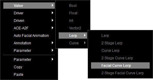
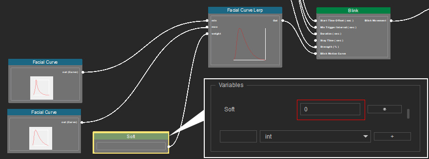
The Facial Curve Lerp node provides 2 input ports: min and max for two different facial performing animation curves, input from the Facial Curve node.
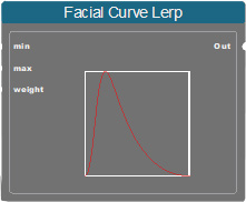
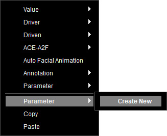
It requires a parameter node to control the weight for output blending. You can create one by right-clicking on the empty area of the graph, and selecting Parameter > Create New from the context menu.
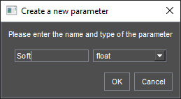
Name the new parameter and choose the "float" type. Click on OK.
Select this node to set a value ranging from 0 to 1 in the Variables section, to perform linear interpolation between the min and max curves. When executed, the Facial Curve Lerp node outputs the interpolated curve based on the parameter value and transmits it to the connected nodes.
For example, create a Facial Curve Lerp node from the context menu Value > Lerp > Facial Curve Lerp to control the blink animation curve.
The Facial Curve Lerp node provides 2 input ports: min and max for two different facial performing animation curves, input from the Facial Curve node.
It requires a parameter node to control the weight for output blending. You can create one by right-clicking on the empty area of the graph, and selecting Parameter > Create New from the context menu.
Name the new parameter and choose the "float" type. Click on OK.
Select this node to set a value ranging from 0 to 1 in the Variables section, to perform linear interpolation between the min and max curves. When executed, the Facial Curve Lerp node outputs the interpolated curve based on the parameter value and transmits it to the connected nodes.
- If the value is set to 0, it uses the min curve.
- If the value is set to 0.5, it calculates the average of the min and max curves and outputs the result.
- If the value is set to 1, it uses the max curve.
Make sure that the data is properly set with Value nodes, before linking the Blink node to an animation trigger node.
