Assigning Node(s) for Controller Handles
No matter your custom accessory is set as single or pair, with bone or hierarchy structure, you need to
define the handles so that the transformations, bones or materials of the
accessory can be puppeteered by the
Controller.
Assign Node(s) for Controller Handles Page - Single or Pair
Because the Assign Node(s) for Controller Handles shows only single chain of bones, the relations between
the Object Structure and the Assign Node(s) for Controller Handles are as shown below:
Single
You need to activate the boxes in this page for the entire accessory to be able to be
set puppeteering data by Builder and be puppeteered by
Controller.

Pair
You need to activate the boxes in these two individual pages for the
bilateral parts of the
accessory to be able to be set puppeteering data by Builder and be puppeteered by
Controller.

Relation between Assign Node(s) for Controller Handles, Define Puppet Behavior and Controller
When you activate boxes in certain column, you are actually define the ability of the node in the tree
view to be set with puppeteering data; and also to be puppeteered for generating animations.
The relation between this page, the next page (Define Puppet Behavior) and the controller are shown
as the illustrations below:
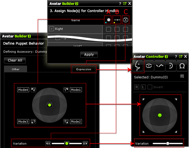
General Accessories - Ears, Eyebrows and Other
When you create accessories of this kind, in this page, you can see up to three
columns that represent the handles of Green Dot, Slider and
Emotion.
-
A: Dot column - Activating the box, of a node, under this column so that
you are able to set the maximum reactions of the node to axes around
the compass in the Define Puppet Behavior page. After you completely set the puppeteering data, you are able to use the similar compass in the Controller
to puppet and record the animations of the accessory.
-
B: Slider column - Activating the box, of a node, under this column so that
you are able to set the maximum reactions of the node
to axes at the both ends of the Variation slider in the
Define Puppet Behavior page. After you completely set
the puppeteering data, you are able to use the
Variation slider in the Controller
to puppet and record the animations of the accessory.
-
C: Emotion column - Activating the box, of a node, under this column so that
you are able to set the maximum reactions of the node
to axes around the compass in the Expression tab in the
Define Puppet Behavior page. After you completely set
the puppeteering data of different expressions, you are able to use the
similar compass in the Controller
to puppet and record the full-face expressions (accessory involved) of the
character.
Eye Accessories
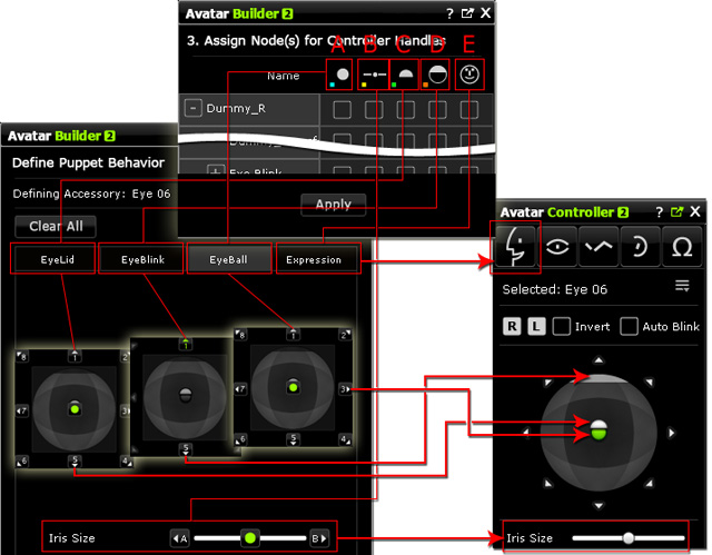
Because the eye accessory is composed of somewhat complicated structure, the columns in this page
are up to five that represent the handles of EyeBlink, EyeLid, Eyeball,
Emotion and Iris Size.
-
A: Eyeball column - Activating the box, of an eyeball, under this column so that
you are able to set the maximum reactions of the eyeball to axes around
the compass in the Define Puppet Behavior >> EyeBall tab. After you completely set the puppeteering data, you are able to use the similar compass in the Controller
to puppet and record the animations of the eyeball.
-
B: Iris column - Activating the box, of a node, under this column so that
you are able to set the maximum reactions of the node
to axes at the both ends of the Variation slider in the
Define Puppet Behavior >> Iris Size slider. After you completely set
the puppeteering data, you are able to use the Iris Size slider in the Controller
to puppet and record the animations of the iris.
-
C: Lid column - Activating the box, of a node, under this column so that
you are able to set the maximum reactions of the eyelid
to axes around the compass in the
Define Puppet Behavior >> EyeLid page. After you completely set
the puppeteering data, you are able to use the similar compass in the Controller
to puppet and record the animations of the eyelid.
-
D: Blink column - Activating the box, of a node, under this column so that
you are able to set the maximum reactions of the eyelid
to axes around the compass in the
Define Puppet Behavior >> EyeBlink page. After you completely set
the puppeteering data, you are able to use the similar compass in the Controller
to vertically puppet and record the animations of the blinks.
-
E: Emotion column - Activating the box, of a node, under this column so that
you are able to set the maximum reactions of the node
to axes around the compass in the Expression tab in the
Define Puppet Behavior >> Expression page. After you completely set
the puppeteering data of different expressions, you are able to use the
similar compass in the Controller
to puppet and record the full-face expressions (eye accessory involved) of the
character.
|
Note:
|
|
-
By activating the box, you define the node to be controlled by
certain controllers listed above.
-
There are three circular phases for each box of a node. These phases determine
the properties of a node to be puppeteered.
-
 :
Not to be set puppeteering data nor to be puppeteered. :
Not to be set puppeteering data nor to be puppeteered.
-
 : Only material can be
set puppeteering data (via Builder) and
be puppeteered (via Controller). : Only material can be
set puppeteering data (via Builder) and
be puppeteered (via Controller).
-
 :
Transformations, bone offsets and materials can be
set puppeteering data (via Builder) and
be puppeteered (via Controller). :
Transformations, bone offsets and materials can be
set puppeteering data (via Builder) and
be puppeteered (via Controller).
|
Color Coding for Highlighted Bones
When you activate the box under certain column, the bone in the preview window
will be highlighted with different colors, which informs you by which handle or handles the
bone is governed. These colors represent the handles in different pages.
General Accessories - Ears, Eyebrows and Other
-
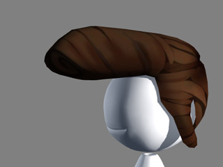
Given a bone-skinned accessory attached to the character.
-
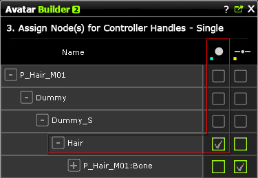
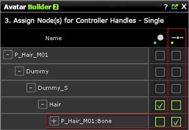
In the Define Controllers >> Assign Node(s) for Controller Handles
page, activate the joints to which you want to set puppeteering data.
|
|
|
Different bones are individually assigned to be under control of
Dot or Slider.
|
-
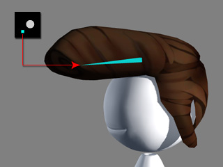
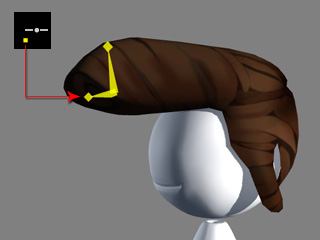
You will see the bone or bones in the 3D view is highlighted in the colors next to the icons of the Dot
and Slider.
|
|
|
Highlighted in Blue: Under Dot control.
|
Highlighted in Yellow: Under Slider
control.
|
-
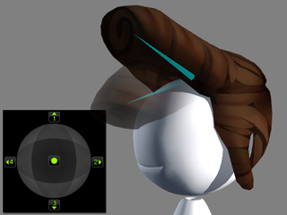
Only the status of the highlighted bones can be kept by using the
handles in the Define Puppet Behavior.
|
|
|
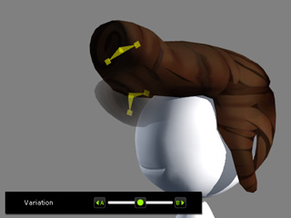
Five postures of the hair are kept into the five axes (up, down, left, right and center)
around the compass.
|
Three postures of the bangs are kept into the three axes (left, right and center) of the slider.
|
Eye Accessories
-
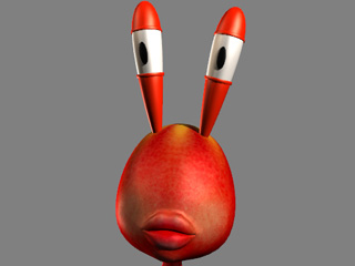
Given a pair of bone-skinned eye accessory attached to the character.
-
Pick one of the eyes and access the Assign Node(s) for Controller Handles
page.
-
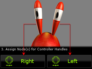
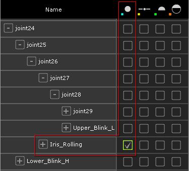
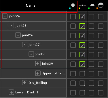
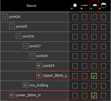
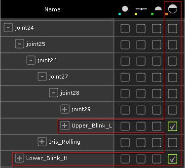
Take the right eye for example, in this page, activate the joints to which
you want to set puppeteering data (in case A, the iris joint, in case B, the kernel joints, in case C, the eyelid joints
and in case D, the eyelid joints for blinking).
|
|
|
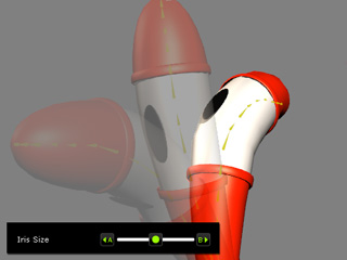
Case A: The joints (iris) under the Eyeball column
are activated.
|
Case B: The joints (kernel) under the Iris column are activated.
|
|
|
|
|
|
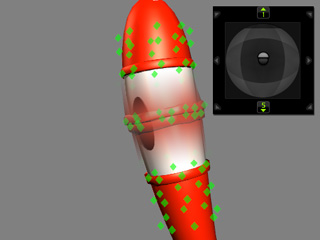
Case C: The joints (upper and lower eyelids) under the
Lid column are activated.
|
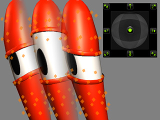
Case D: The joints (upper and lower eyelids) under the
Blink column are activated.
|
|
Note:
|
|
Because in this case, the iris is not going to enlarge or
shrink, the Iris slider is taken for bending the
entire eye component. That is the reason why the kernel
joints are all activated under the Iris slider
column in case B.
|
-
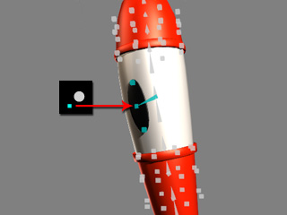
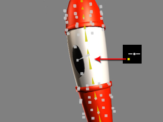
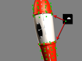
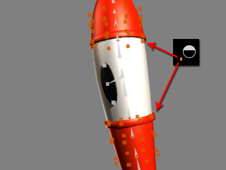
You will see the bone or bones in the 3D view is highlighted in the colors next to the icons of the
Eyeball, Iris, Lid and Blink.
|
|
|
Case A: The activated box causes the bone to be highlighted in
blue.
|
Case B: The activated boxes cause the bones to be highlighted in
yellow.
|
|
|
|
|
|
Case C: The activated box causes the bone to be highlighted in
light green.
|
Case D: The activated boxes cause the bones to be highlighted in
orange.
|
-
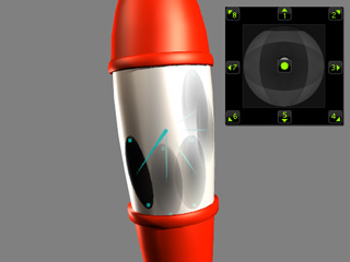
Only the status of the highlighted bones can be kept by using the
handles in the Define Puppet Behavior (in this case, the compass
for case A, C, D and the slider for case B)
page.
|
|
|
Case A: Nine postures of the iris are kept into the
nine axes (up, down, left, right, top-left, top-right,
bottom-left, bottom-right and center) of the compass.
|
Case B: Three postures of the eye are kept into the three axes (left, right and center) of the slider.
|
|
|
|
|
|
Case C: Two postures of the eyelids are kept into the five axes (up, down and center) of the compass.
|
Case D: Nine postures of the eyelids are kept into the nine axes (up,
down, left, right, top-left, top-right, bottom-left,
bottom-right and center) of the compass.
|
|
Note:
|
|
-
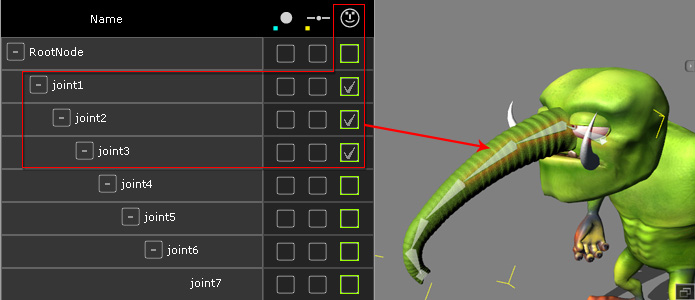
If one or more joints are not highlighted with
any colors, then it could be
either free from being controlled or controlled by the Expression
controller.
|
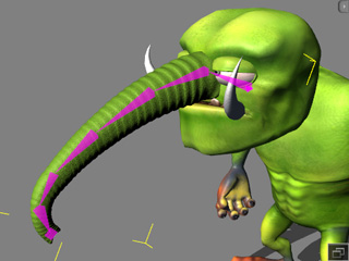
Special Color Code - Magenta
When you need a joint to be able to be given puppeteering data, you may need to horizontally activate
the boxes for that joint. The highlighting color will turn to magenta, which notifies you that the
joint can be set with individual postures in different controllers.
The ability to be controlled by different controllers influences the use of Controller
for setting key pose as described below:
-
Take the elephant nose accessory as the one in the note box above.
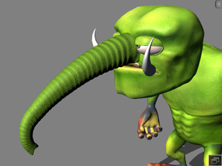
-
Set the parameters with Builder as shown below:
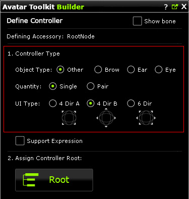
-
Click the Assign Controller Handles and horizontally activate the
boxes as shown below:
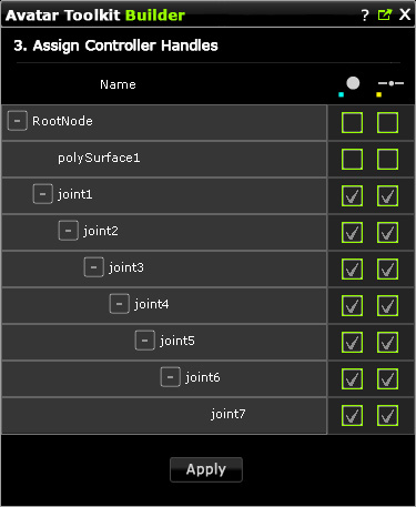
You may see that the joints with horizontally activated boxes are highlighted
in magenta.
-
Apply the settings and go to the Define Puppet Behavior page.
-
Set postures to the axes around the compass and the slider.
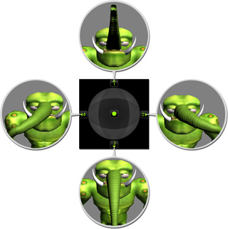
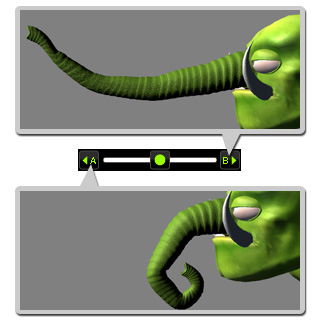
-
Click the OK button to save the data to the accessory.
-
Apply the Controller prop. You will see
the Controller panel shows. Select the accessory and switch to
the Other tab.
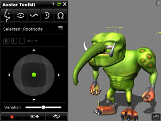
-
Press down the Add Key button at the bottom of the panel.

-
Drag the green dot of the compass to an axis to set a posture
key (defined previously) for the accessory.
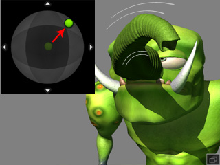
-
Drag the slider to an axis as well. You will find the posture you set
in the last step is replaced by the one you have defined in the
axes of the slider.
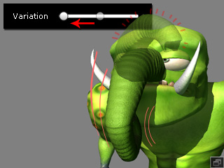
You can not blend different postures from different handles to
set pose keys.
|
Note:
|
|
-
In order to blend up the posture from different handles, in
step 3, you shall not horizontally activate boxes for one joint.
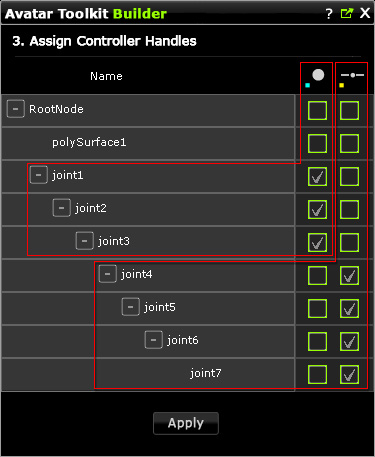
-
The accessory can then be set posture keys by
blending from different handles.
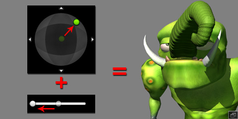
-
Please note that since the puppeteering of the accessory generates
animation clips instead of animation keys, the previously recorded
clip will
always be replaced by the later recorded one
(no layer-recording technique), no matter
if the boxes of a joint are horizontally checked or not.
|


