Building Behavior Logic
The Graph Editor lets you easily manage and edit your simulation scripts. Use nodes to chain human actions, expand scripts, or define conditional logic, making your simulations more realistic, natural, and flexible.
When recreating a real-world environment using MD Props, once the MD Props are applied, you can use the Motion Planning Graph panel to connect scene object motions with their corresponding nodes. This allows characters to automatically interact with Props and MD Props in Go MD mode.
- In the Content Manager, switch to Props > MD Props. You will see various MD Dummy Props.
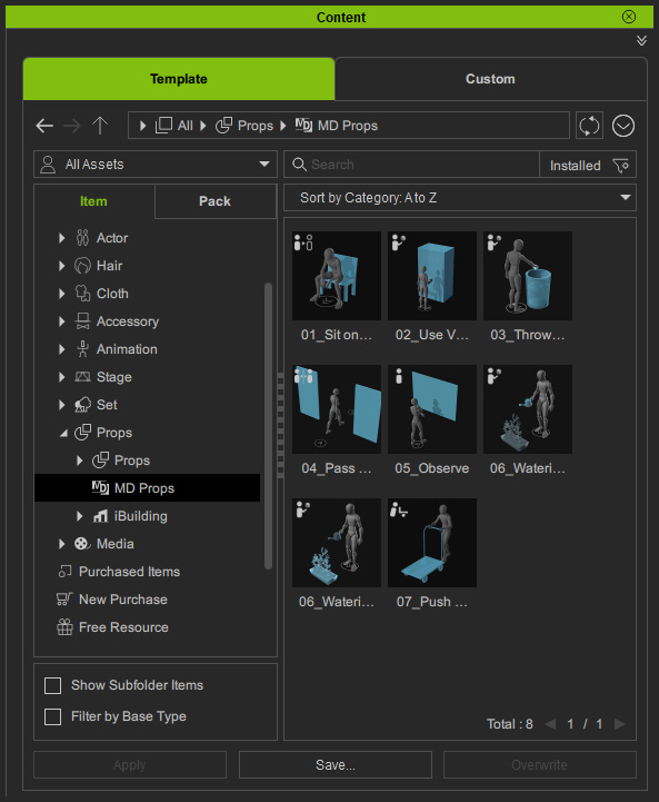
- Drag and drop the desired MD Props into the scene and reposition them.
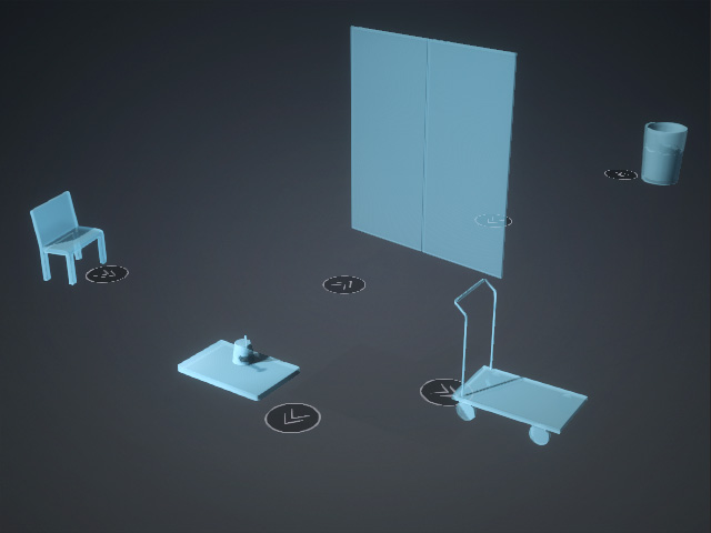
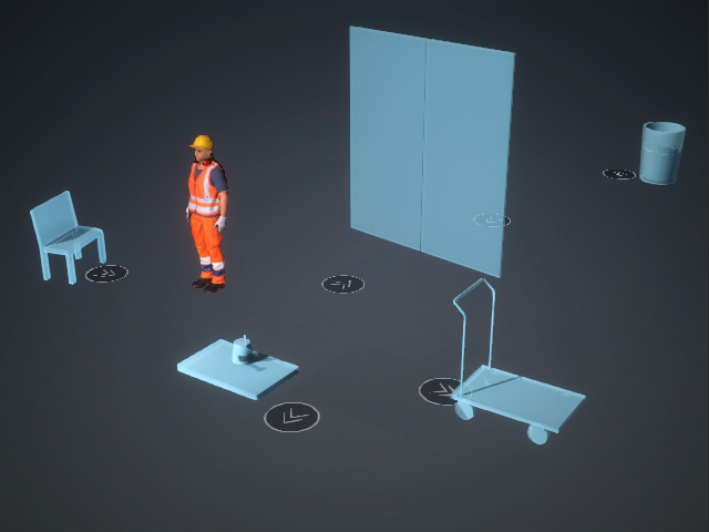
- Add the desired character to the scene.
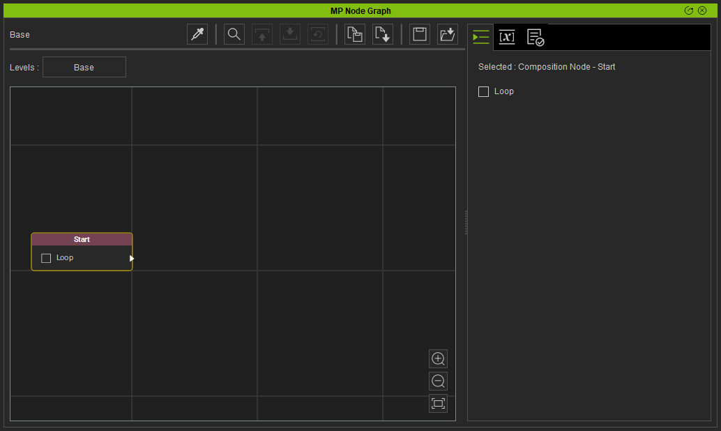
- Open the MP Node Graph panel and make sure the Start node is selected.
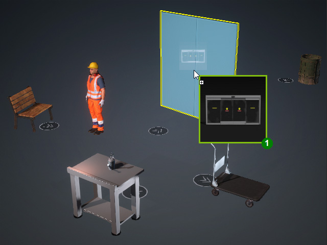
- Use the Pick from Scene tool to add a node corresponding to an object from the 3D viewport.
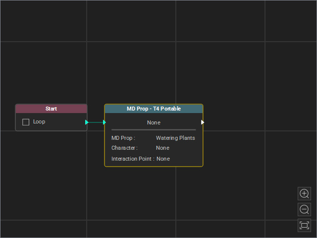
Note that the object name is automatically filled into the node, while the other fields remain blank (None).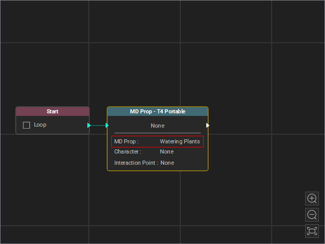
- Repeat these steps until you finish adding object nodes, then add logic nodes (Flow, Condition and some Motion nodes) and nodes for printing message in the 3D viewport.
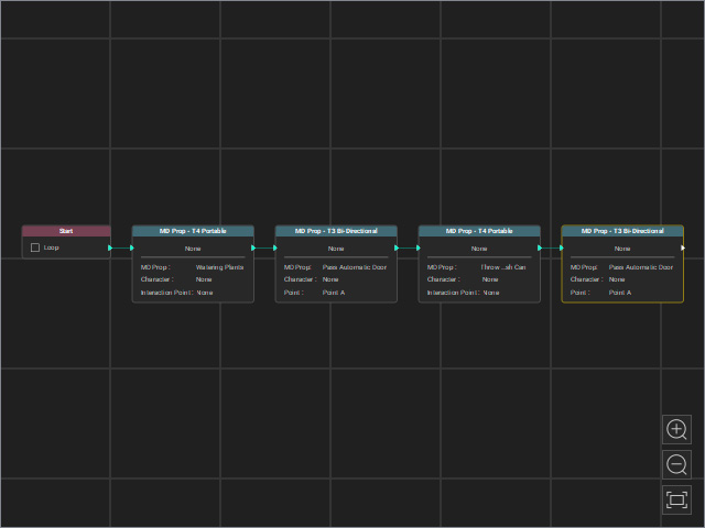
Organize the layout as needed, optionally using Composition Nodes, for better readability.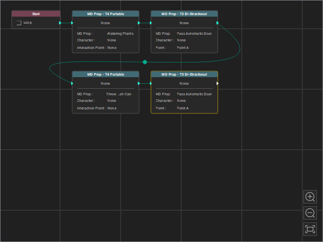
- Manually add nodes to the viewport.
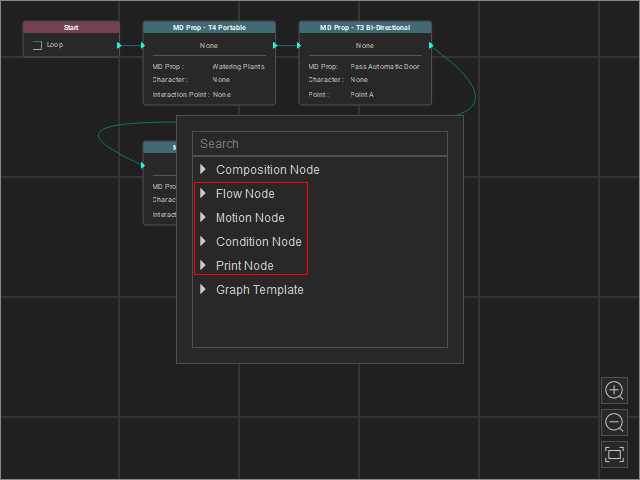
In this example, a Flow Node > Random node is used.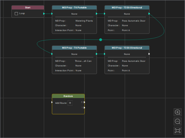
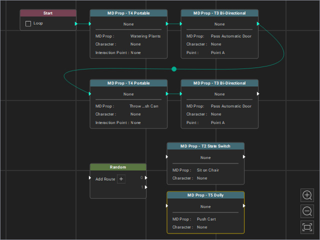
- Pick nodes from the scene again, since auto-connection does not occur when a Flow Node is selected.
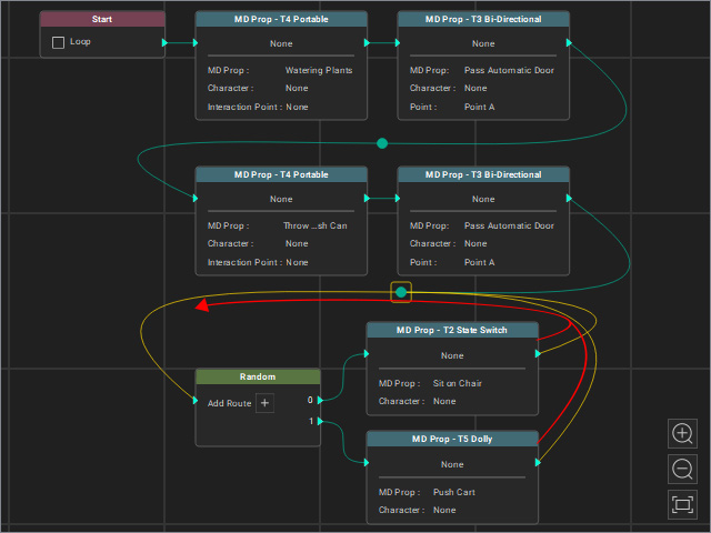
- Manually connect the nodes.
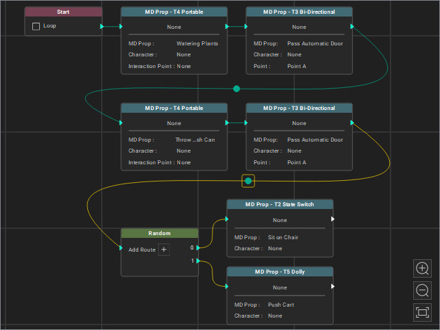
- To create a looping animation, connect the outputs of the last nodes back to the logic node.
- Using the Swap Actors feature to assign the character to multiple nodes at once.
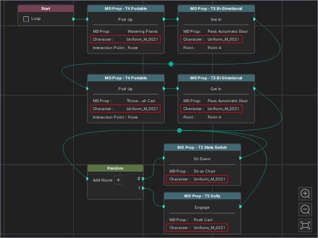
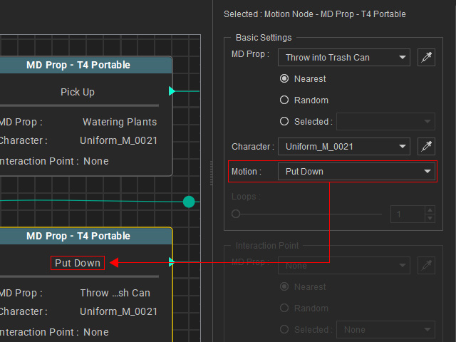
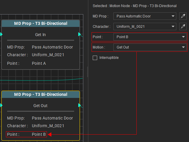
- Manually adjust the node settings according to your intended behavior.
- Optionally, replace the dummy MD Props with actual props by dragging and dropping them with the right mouse button.
- Start Go MD mode to view the animation result.
