Defining Controller Settings

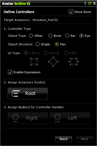
In the Define Controllers page, all you need to do is to set the user interface of the Controller and to let the Builder know which object should be governed by what controller handles through mapping the object nodes to the handles.

How to get started

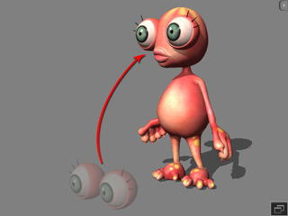
  1. Attach the eye prop to the head of a character. This step converts the prop into an accessory and CAN NOT be skipped.

    It is highly recommended that you follow the steps described in the Creating Eye Accessories and Preparing Custom Accessory sections to create the eye prop.
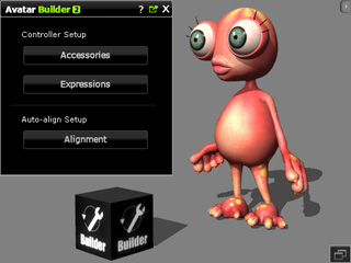
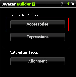
  2. Drag and drop the Builder into the 3D preview window; you will see the Builder panel displays.
  3. Click the Accessories button and then pick the eye accessory.
  4. The builder window will switch to the Define Controllers page.

Defining Controllers for a Selected Accessory

1. Controller Type

This step defines the appearance of the controller for the picked accessory.
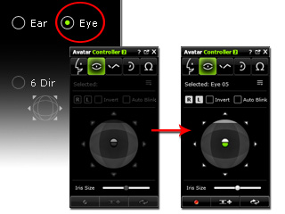
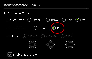
  1. Set the Object Type by choosing the Eye radio button so that the controllers within the Eye tab of the Controller panel are enabled.
  2. Select the Pair radio button.
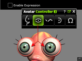
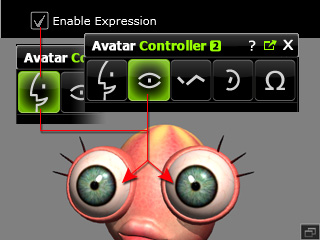
  3. If you want this accessory to also be puppeteered via the controller in the Expression tab, then activate the Enable Expression box.

    Enable Expression: OFF.

    The controller in the Expression tab of the Controller can not control the eye accessory. Only the one in the Eye tab can.

    Enable Expression: ON.

    Both the controllers in the Expression and Eye tab of the Controller can control the eye accessory.

2. Assign Accessory Root(s)

After the eye accessory is set as Pair one in the previous step, this step splits the tree structure of the entire eye accessory into right and left sub trees for the individual eyes. Only the nodes under the sub trees can thus be set to be involved in the puppeteering procedure. It also influences the nodes to be displayed in the next step.

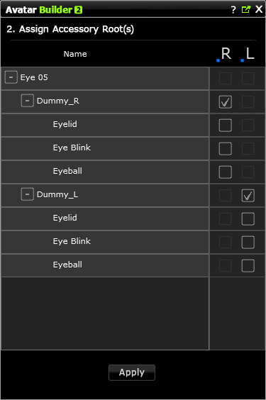
  1. Click the Root button. The entire panel will switch to the Assign Accessory Root(s) page.
  2. Activate the root nodes respectively for the L and R column.
  3. Click the Apply button to keep the settings to the eye accessory.
  4. The Root button will become highlighted to inform you that the roots of the eyes have been set.

    Note:

3. Assign Node(s) for Controller Handles

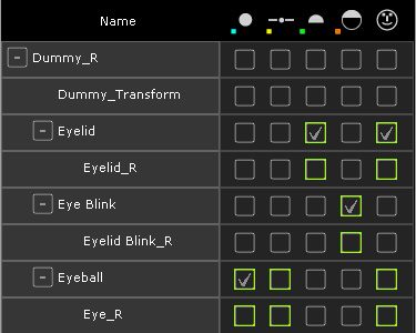
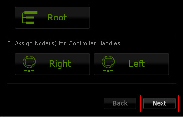
As soon as you have chosen the Pair radio button and have assigned the root for the left and right eyes in the previous steps, the Right and Left buttons under this step will be enabled. You may then individually click these buttons and pick the nodes to define the properties (position, angle and material) of the nodes to be animated by the Controller.

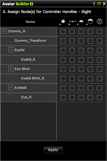
  1. Click the Right button.
  2. The Builder will switch to the Assign Node(s) for Controller Handles mode.
  3. Only the structure of the right eye is shown in the panel.
  4. Click on the boxes to determine the properties of a node to be animated by controllers.

    Note:

  5. Click the Apply button to keep the settings to the right eye of the eye accessory.
  6. Repeat the same steps for the left eye.
  7. The Right and Left button will be highlighted to inform you that the nodes of the eyes have been appropriately assigned.

    Click the Next button to set the values of properties for the nodes and move on to the Puppet Behavior Setting page.